This article contains information regarding the configuration and installation of MV4th16 Forth on various types of Parallax Propeller boards. The article includes information on configuring; the system clock, the asynchronous serial UART, the I2C buss and the block storage device. Starting with MV4th16 version 0.94 support was added to use an SD card as block storage. Prior versions where limited to an EEPROM for block storage.
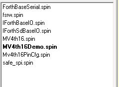
The MV4th16 software source and example files are distributed in a zip format file. The newest version of MV4th16 source file can be found in the MV4th16 Downloads section of this WEB site. MV4th16 Forth for the Parallax Propeller chip must be compiled using the Parallax IDE. At the time of this article I used version 1.32 of the IDE software. The main project files are in the root of the folder in the install zip file. Unzip the files under your preferred Parallax IDE working folder. While using the Parallax IDE select the "PSF" folder and select the "MV4th16Demo.spin" file as the current "Top Object" in the IDE.
Image shows MV4th16 project files as listed in Parallax IDE
Setting the system clock frequency for the Propeller chip:
Open the "MV4th16Demo.spin" file in the IDE. The system clock is set at the top of the document. The system frequency is set in two parts; the phase-locked loop multiplier, and the crystal frequency. Most Propeller boards use a 16 times multiplier for the phase locked loop and a 5.00Mhz frequency crystal for a system clock of 80Mhz. Other settings are possible such as a 6.00Mhz crystal for a 96Mhz system clock, or a 6.25Mhz crystal yielding a 100Mhz system clock frequency.
Image shows Propeller chip system clock settings in "MV4th16Demo.spin" file
Configure default MV4th16 UART Baud Rate:
With the "MV4th16Demo.spin" file open in the IDE go to the bottom of the file and set the default baud rate for the UART device. The UART baud rate is normally set to 115200 bits/second. If you want to use a lower baud rate change the setting to the desired baud rate (300 to 115200 baud).
Image shows UART baud rate setting in "MV4th16Demo.spin" file
Selecting EEPROM or SD-Card as block device:
With the "MV4th16Demo.spin" file open in the IDE go to the "OBJ" section of the file and select the desired forth base I/O object. To use an EEPROM device as the Forth block device include the "IForthBaseIO" object as the IO object. To use an SD-Card as the forth block device select the "IForthSdBaseIO" object as the IO object. Due to the fact that the Propeller IDE has no macro support remove the comment symbol from the desired line (remove apostrophe at start of line) and comment out the line not being used (add apostrophe to start of line)..
Image shows selection of block device type, EEPROM select as block device
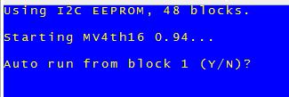
Image shows MV4th16 starting using EEPROM as block device:
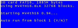
Image shows MV4th16 starting using SD-Card as block device:
Selecting Propeller Chip I/O pins:
The hardware pin numbers used for the 2 wire serial port, the mode 0 I2C buss, and 4 wire SPI buss for the SD-Card (if used) are configured in the project file "MV4th16PinCfg.spin".
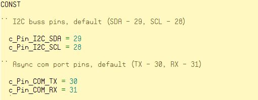
The pin settings for the 2 wire serial port are set by default to use pins 30 and 31, these pins are normally connected to the Parallax prop-plug or FTDI USB to serial device. The serial port is used by MV4th16 as the default console device (COM1). If you do not want to use the default serial port pin numbers they may be changed at the top of the file.
MV4th16 implements a simple Mode 0 I2C interface using Propeller pin numbers 28 and 29 by default. If you are using an EEPROM as the forth block device, the EEPROM must be connected to the configured I2C interface pins. If you choose to use an SD-Card as the forth block device the I2C buss can still be used to access mode 0 compatible I2C devices connected to the I2C buss pins.
Image shows 2 wire serial and I2C pin settings;
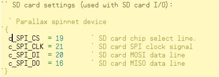
Below the pin settings for the com port in the "MV4th16PinCfg.spin" file are the settings for the SD-Card SPI interface pins.
Image shows SD-Card SPI pin settings;
There are no default settings for the SPI buss on a Propeller chip. The selected pin numbers should reflect the connected SD-Card configured for standard SPI mode access. The default configuration file includes the pin settings used by the Parallax "SpinNet" board to access the on-board SD-Card slot. Any unused pins may be used to implement the SD-Card SPI interface. If the object "IForthBaseIO" is selected in the "MV4th16Demo.spin" file the SPI pin settings are ignored.
Choosing The Serial Port TX Pin Output Mode:
At the bottom of the "MV4th16PinCfg.spin" file is a setting to control weather the serial TX pin is configured to used open drain or push\pull output drive mode. If the open drain option is used a 25k..50k pull-up resistor should be connected to the serial port TX pin.
Normally push\pull mode should be used when there is no FTDI USB to serial IC connected to the TX output pin.
If an FTDI USB IC is connected to the default serial TX pin on the Propeller chip and the DTR output is coupled to reset pin on the propeller chip the Propeller chip may constantly be reset by the FTDI IC when the FTDI IC is not connected to a USB host. The reset is caused when the TX pin is set high by the propeller chip and no power is applied to the FTDI IC. A high level on the Propeller TX line will cause the FTDI IC to be powered up through its reverse protection diodes. When the FTDI powers up it will set the DTR output high and will cause the Propeller chip to reset. A high value pull-up resistor attached to the Propeller TX pin limits the current on the FTDI device input to a level that can not initialize the FTDI IC. The open drain configuration can now safely drive the FTDI USB serial IC.
Image shows configuration setting in "MV4th16PinCfg.spin" to set serial TX drive mode
The serial port RX pin must be set to a logic high when no data is begin received. If the Propeller RX pin is left to float it may float to a logic low level causing invalid characters to be received by MV4th16. To prevent invalid characters a 25K..50K pull-up resistor should be connected to the serial port RX pin on the Propeller chip.
NOTE: I generally use 33K resistors on both the RX and TX pins on the Propeller chip.
Using EEPROM as a Forth Block Device Under MV4th16:
If you are using an EEPROM device for the Forth block storage you will need to set the parameters for the EEPROM in the "IForthBaseIO.spin" file. At the top of the "IForthBaseIO.spin" file set the EEPROM read and write commands. Normally the base EEPROM address is hex A0 to write the EEPROM and A1 to read the EEPROM If you add a second EEPROM device to the existing I2C buss (pins 28, 29) then the I2C address will need to be changed using the address pins on the EEPROM device. The new command addresses must be used to correctly set the c_EEpromAdrTx, and c_EEpromAdrRx constants at the start of the "IForthBaseIO.spin" file.
There are three additional EEPROM settings required:
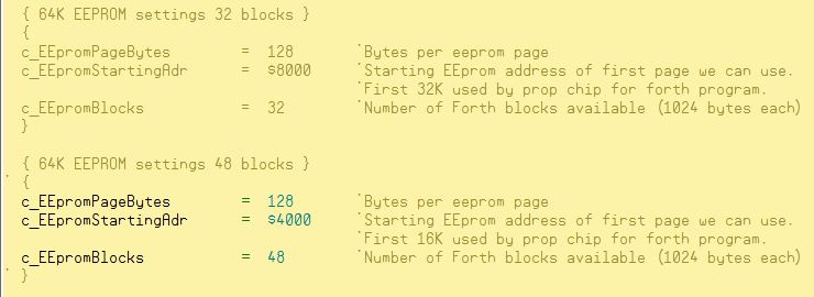
- c_EEpromPageBytes -- number of bytes in a single EEPROM page (ex: 32K = 64 bytes, 64K = 128 bytes, 128K = 256 bytes)
- c_EEpromBlocks -- number Forth 1K blocks on the EEPROM device.
- c_EEpromStartingAdr -- EEPROM byte address of first EEPROM page used by Forth for block storage (normally $4000 = skip first 16K bytes, $8000 = skip first 32K or 0 to use entire EEPROM).
The EEPROM device used for Forth block storage can either be the EEPROM used for the boot image by the Propeller chip or a dedicated EEPROM. The default I2C address for the boot image EEPROM on a Propeller chip system is A0 hex.
If you want to use the Propeller chip's default I2C pins (pins 28 & 29) to connect a dedicated EEPROM, the new EEPROM will have to be mapped to a higher address by setting the address using EEPROM address pins. Do not forget to update the EEPROM address at the top of the "IForthBaseIO.spin" file.
If you want to use the Propeller chip's boot EEPROM as block storage you need to decide how much space to reserve for the Propeller chip boot image. Currently the boot image for MV4th16Demo using EEPROM block storage is slightly less then 16K. So if we have a 64K EEPROM boot device we can support up to 48 1K Forth blocks. The rub comes due to the fact that the Parallax IDE will always erase and program the first 32K of the EEPROM regardless of the size of the boot image. This will erase the first 16 1K forth blocks any time the boot image must be updated.
If you can not tolerate the Forth blocks being erased by the reloading of the Propeller chip boot image you have two choices:
1) set the stating address of the block storage to 32K .
2) use a dedicated EEPROM as your Forth block storage device. There are a number of commonly used EEPROM setting commented out for the Forth block storage on an EEPROM at the start of the "IForthBaseIO.spin" file.
Image shows some of the possible EEPROM settings in the "IForthBaseIO.spin" file
Using the SD-Card as Forth Block Device Under MV4th16:
Once you have selected the "IForthSdBaseIO" object as the IO object in the "MV4th16Demo.spin" file, and set the pin numbers for the SPI buss in the MV4th16PinCfg.spin" file you are ready to use an SD-Card as the Forth block device.
The SD-Card must be formatted as FAT32 or FAT16 file format. The SD-Card may not contain any files or directories before the forth block storage file is created on the SD-Card. The forth block storage file must be named "MV4TH16.BLK" and must be in the root directory of the FAT partition. The forth block storage file can be 1 MB to 63 MB in size. The "MV4TH16.BLK" file should be initialize with character 32 (space char).
When MV4th16 is started and a freshly formatted SD-Card is detected MV4th16 will offer to create the "MV4TH16.BLK" file. If you select "Y" to the create file prompt you will be asked for a file size in mega-bytes. Once the size is input the MV4th16 system will create the new block file before starting MV4th16. A 1 MB block file will hold 1024 blocks and a 32M file will hold 32768 forth blocks.
Image shows MV4th16 at startup, blank SD-Card detected:


