


This article contains information regarding the I/O devices implemented in the first prototype for the Mini80 project. The first prototype of the Mini80 implements a number of I/O devices such as; 4 channel floppy disk controller, 3 serial UARTS, and access to read files from the FAT partition on the SD card used to store the CPM floppy disk images.
All I/O peripheral devices are implemented by a Parallax Propeller chip. The peripheral devices implemented by the Propeller chip are accessed by the Z80 via the Z80 "port" instructions that generate I/O port access signals (/IOREQ = low).
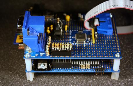
Min80 board with I/O board on top
The Mini80 Propeller chip code splits the Z80 port map in to two regions. Port addresses 00h to 1Fh are handled by the Propeller COG controlling the Z80 CPU directly. The remaining port addresses, 20h to FFh are passed to a spin process. Each of the peripherals attached to the Z80 is manipulated by reading and writing the port addresses mapped to the specific device. For the first prototype of the Min80 all peripheral devices and there port addresses are listed below;
UART 1 port mappings (ports 00h, 01h, and 20h)
The UART 1 device is used for asynchronous serial data transmission. The UART is full duplex and supports 7 and 8 bit data transmission. When using 7 bit transmission an optional parity bit (odd/even) can be appended to the data. The UART supports 1 or 2 stop bits per data byte in transmit mode. The UART optionally supports hardware based flow control (RTS/CTS).
- 00h -- is used to transfer data between the Z80 and the UART. A read of the port returns the next available data byte from the receive fifo buffer. A write to the port adds a data byte to the transmit FIFO buffer.
- 01h -- is the UART FIFO status and clear FIFO control register. A read of port 01h returns the FIFO status as a bit mapped byte. The following bits are used to represent the state of the UART FIFOs;
0 -- device active, high when the UART is enabled, low when the device is inactive.
1 -- receive FIFO state, high when data is available from the receive FIFO, low when the receive FIFO is empty.
2 -- transmit FIFO state, high when data can be written to the transmit FIFO, low when the transmit FIFO is full.
3 -- transmit FIFO empty, high when the transmit FIFO is empty, low when the transmit FIFO has data to send.
A write to port 01h controls the FIFO clear functions. The following bits are used to control the clearing of the UART FIFOs;
0 -- N/U should be set to high.
1 -- clear UART receive FIFO buffer.
2 -- clear UART transmit FIFO buffer. -
20h -- is used to read and write the UART data format and baud rate. The lower nibble controls the baud rate the remaining bits configure the UART data format. The following bits are used to represent the configuration of the UART;
0 .. 3 -- baud rate selection, the following baud rates are supported;
%0000 - 300 baud
%0001 - 600 baud
%0010 - 1,200 baud
%0011 - 2,400 baud
%0100 - 3,600 baud
%0101 - 4,800 baud
%0110 - 7,200 baud
%0111 - 9,600 baud
%1000 - 14,400 baud
%1001 - 19,200 baud
%1010 - 28,800 baud
%1011 - 38,400 baud
%1100 - 57,600 baud
%1101 - 76,800 baud
%1110 - 115,200 baud
%1111 - 130,200 baud
4 .. 5 -- bits 4 and 5 control the data format;
%00 - 7 bits data no parity bit
%01 - 7 bits data odd parity bit
%10 - 7 bits data even parity bit
%11 - 8 bits data no parity bit
6 -- number of stop bits, low for 1 stop bit, high for 2 stop bits
7 -- controls hardware hand shaking, a high turns on hardware hand shaking, a low disables hardware hand shaking.
UART 2 port mappings (ports 02h, 03h, and 21h)
The UART 2 device is used for asynchronous serial data transmission. The UART is identical to UART 1 but uses ports 02h for data, 03h for status/FIFO control and 21h for data format and baud rate.
UART 3 port mappings (ports 04h, 05h, and 22h)
The UART 3 device is used for asynchronous serial data transmission. The UART is identical to UART 1 but uses ports 04h for data, 05h for status/FIFO control and 22h for data format and baud rate. UART 3 is a two wire serial port and does not support the hardware flow control signals.
Z80 CPU Frequency (port 08h)
The master clock signal for the Z80 CPU is generated by the Propeller chip. Port address 08h is used to read and write the desired Z80 clock frequency. The frequency can be set from 0.1MHz to 25.5MHz in 0.1MHz steps. As an example writing the decimal value 52 to port 08h will set the Z80 frequency to 5.2MHz. If a value of zero is written to the port the Min80 system will reboot.
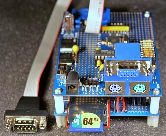
Standard SD card to store CPM disk images and other files.
Floppy Disk Controller (ports 10h...1Fh)
The Propeller chip is used to emulate a four drive floppy disk controller. From 4 to 128 CPM floppy disk images are stored in a disk pack file called "CPMDISK.CDP". The disk pack file must be in the root folder of a FAT16 or FAT32 formatted SD card. The disk controller can control up to 4 disk drives. Any of the disk pack floppy disk images can be mounted into any one of the 4 disk drives. Each floppy disk sector contains 128 bytes of data. The disk controller allows the reading and writing of any 128 byte CPM standard sector on any of the four disk drives. To read or write a disk sector the Z80 first sets the following ports; Disk Select, Sector number, and Track number.
If a read disk sector is to be performed the Z80 writes the read command byte to the disk controller command port. The Z80 then reads the disk controller status port to determine if the request completed properly. If there is no error (status = 0) the Z80 can read the disk sector data bytes from the disk controller sector buffer. The Z80 first sets the sector buffer address port to 0. Next the Z80 reads the disk controller sector buffer data port 128 times to read the disk sector data. The sector buffer address port will auto-increment each time a byte of data is read from the sector buffer data port.
If a write disk sector is to be performed the Z80 must write 128 bytes of data to the disk controller sector buffer. The Z80 first sets the sector buffer address port to 0. Next the Z80 writes to the disk controller sector buffer data port 128 times to write the disk sector data. The sector buffer address port will auto-increment each time a byte of data is written to the sector buffer data port. Next the Z80 writes the write sector command byte to the disk controller command port. The Z80 then reads the disk controller status port to determine if the request completed properly. If there is no error a read of the disk controller status port will equal to 0.
The floppy disk controller uses 4 port addresses to select which of the possible (4 to 128) floppy disk images are mounted in a specific disk drive. The floppy disk images are numbered from 0 to 127 where the max disk number is controlled by the size of the CPM disk pack file on the SD card. There is an additional 4 port address the are used to hold the one byte disk attribute flags, one port for each disk drive. Currently the disk controller support the boot attribute and the read only attribute.
The following port addresses are used by the disk controller;
- 10h -- write command register, read status register. When the port is read the status from last disk controller command is returned as;
0 - last command completed with no error.
1 - set to 1 when a home disk request failed.
2 - set to 1 when a read sector request failed.
4 - set to 1 when a write sector request failed.
8 - set to 1 if disk index is out of range for mounted disk pack.
16 - set to 1 when disk controller is busy with last request.
Writing to this port sets the disk controller command register and begins execution of the requested command. Valid command values are;
0 - reset disk controller
1 - home selected disk
2 - read selected disk sector
3 - write selected disk sector - 11h -- read or write disk drive select register. Selected disk drive (0..3), actual floppy disk index stored in disk select registers 18h to 1Bh.
- 12h -- read or write low byte of 16 bit sector number.
- 13h -- read or write high byte of 16 bit sector number.
- 14h -- read or write low byte of 16 bit track number.
- 15h -- read or write high byte of 16 bit track number.
- 16h -- read or write data byte from disk controller sector buffer. The address of the byte transferred is the value stored at port 17h.
- 17h -- read or write current sector buffer address pointer (0...127). Address value is auto-incremented after each data byte is read or written.
- 18h -- read or write disk drive 0 floppy disk image index number. Used to select/read which floppy disk is mounted in drive 0.
- 19h -- read or write disk drive 1 floppy disk image index number. Used to select/read which floppy disk is mounted in drive 1.
- 1Ah -- read or write disk drive 2 floppy disk image index number. Used to select/read which floppy disk is mounted in drive 2.
- 1Bh -- read or write disk drive 3 floppy disk image index number. Used to select/read which floppy disk is mounted in drive 3.
- 1Ch -- read or write disk drive 0 attributes. Only the read-only attribute is used by the disk controller. Attribute values are 1 for boot flag, 2 for read-only flag.
- 1Dh -- read or write disk drive 1 attributes. Only the read-only attribute is used by the disk controller. Attribute values are 1 for boot flag, 2 for read-only flag.
- 1Eh -- read or write disk drive 2 attributes. Only the read-only attribute is used by the disk controller. Attribute values are 1 for boot flag, 2 for read-only flag.
- 1Fh -- read or write disk drive 3 attributes. Only the read-only attribute is used by the disk controller. Attribute values are 1 for boot flag, 2 for read-only flag.
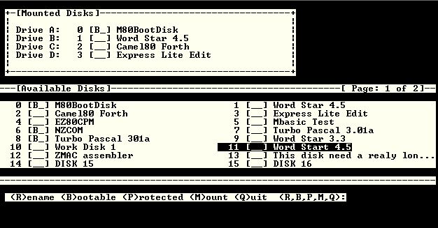
Mini80 AMOUNT.COM program to mount floppy disk images in to disk drives.
Floppy Disk Attribute Controller (ports 30h..35h)
The floppy disk attribute controller allows the Z80 CPU to enumerate and change the attributes of the floopy disk images stored in the disk pack file "CPMDISK.CDP". The floppy disk attribute controller can be used to read and write the CPM floppy disk image display name and disk attributes.
To provide access to the floppy disk display names the controller implements a 32 byte name buffer. The disk name buffer works in much the same way as the sector buffer in the disk controller. Once the floppy disk image index select register is set a command can be requested to set/read the display name of the selected floppy disk image. The results of the command request can be read from the status register. Once a disk image is selected the disk attribute register can be read/written to read or set the floppy disk image attributes byte. The the CPM "AMOUNT.COM" program uses this API to allow the disk images to be mounted in to a specific disk drive as well as rename and change the attributes of the floppy disk images stored in the disk pack file.
The floppy disk attribute controller registers are read/written using the following port numbers;
- 30h-- read status, write command. A read of this port will return the results of the last disk attribute controller command executed. A value of 0 indicates that the command was completed with no error. The error numbers are the same as for the disk drive controller status register (port 10h). Writing a value to this port is used to issue a command to the floppy disk attribute controller. Valid command values are 1 to read a disk name, and 2 to write a disk name.
- 31h -- read/write selected floppy disk image index, used to select the floppy disk image index (0..127) to be used for display name and attribute commands.
- 32h-- read/write disk display name buffer address (0..31). The value in this register is used when reading/writing data bytes to the disk name buffer via port 33h. The address value is auto-increments after each byte is transferred with the disk name buffer.
- 33h -- read or write a data byte from floppy disk attribute controller display name buffer. The address of the byte transferred is the value stored at port 32h.
- 34h -- read the number of disk images contained in the current "CPMDISK.CDP" file.
- 35h -- read/write the attributes byte for the disk image selected using port 31h.
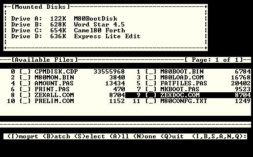
Min80 "FATFILES.COM" program to import fat files to CPM disk
Fat File Access Controller (ports 0Fh, 17h, 30h, 32h, 33h, 36h..3Ah)
The fat file controller allows the Z80 to read and enumerate files stored in the root directory of the SD card. This allows CPM programs to import files stored on the SD card. The fat file controller shares the disk drive controller's sector buffer ports and the floppy disk attribute controller's disk name buffer and command/status ports.
- 0Fh -- read or write data byte from fat file sector buffer. The address of the byte transferred is the value stored at port 17h.
- 17h -- read or write current fat file sector buffer address pointer (0...127). Address value is auto-incremented after each data byte is read or written.
- 30h -- read status, write command. A read of this port will return the results of the last fat file controller command executed. A value of 0 indicates that the command was completed with no error. The error numbers are the same as for the disk drive controller status register (port 10h). Writing a value to this port is used to issue a command to the fat file attribute controller. Valid command values are;
3 - read first fat file name from root directory, name is returned in fat file name buffer. the size of the fat file can be read using ports 37h...3Ah. execute command 4 to read remaining file names and 32 bit byte size.
4 - read next fat file name from root directory, name is returned in fat file name buffer (ports 32h and 33h), and the size in ports 37h..3Ah..
5 - open a fat file for reading, the file name must be set in the fat name buffer (ports 32h and 33h)
6 - read a sector of the fat file in to the disk controller sector buffer (port 16h and 17h).. The number of bytes read can be determined by reading the value of port 36h.
7 - close the open fat file. - 32h-- read/write fat file name buffer address (0..31). The value in this register is used when reading data bytes from the fat file name buffer via port 33h. The address value is auto-increments after each byte is transferred with the fat file name buffer.
- 33h -- read or write a data byte from floppy disk attribute controller fat file name buffer. The address of the byte transferred is the value stored at port 32h.
- 36h-- read the number of bytes place in to the fat file sector buffer after the last successful read fat file command is executed (0..128).
- 37h -- read byte 0, LSB of 4 byte (32 bit) fat file size after command 3 or 4 is executed.
- 38h -- read byte 1 of 4 byte (32 bit) fat file size after command 3 or 4 is executed.
- 39h -- read byte 2 of 4 byte (32 bit) fat file size after command 3 or 4 is executed.
- 3Ah -- read byte 3, MSB of 4 byte (32 bit) fat file size after command 3 or 4 is executed.
CPM Character Device Control Ports (48h and 49h)
The character device control ports are primarily intended to be used by the BIOS and boot loader at start up. Port address 48his used to pass the start-up value for the CPM IOBYTE variable. This controls which CPM logical character devices are mapped to which physical CPM character devices at start-up. Port 49his used to write data to the currently selected CPM console character device. Port 49h can be used by the CPM boot loader to display information or error messages during the boot loader operation.

