
This article introduces the Min80 project. The Mini80 project is a Zilog Z80 based CPM 2.2 computer. All the computer peripherals are emulated using a Parallax Propeller chip. The Propeller chip is used to provide a boot loader for the Z80 CPU, four CPM disk drives (uses SD card), 3 COM ports (2 are 4 wire, 1 is 2 Wire) and read access to the root folder of the files stored on the SD card. The two main constraints for the project where; a real Z80 CPU (no emulation), and keep the project as simple as possible. The first prototype uses the PropTerm project as the system terminal.
The Z80 CPU has been around since the early 1980s. The original Z80 CPU core is still produced today in a 5 volt CMOS form. The Parallax Propeller chip is a 3.3 volt MOS based core. With its 8 CPU cores and 32K of shared memory the Propeller chip can be used to emulate the typical hardware found on a Z80 CPM system from the 1980s. The project is based on two main properties of the Z80 CPU; the fact that it is CMOS; and the fact that the Z80 is a static integrated circuit.
The CMOS construction of the Z80 should allow the Z80 to operate at a reduced voltage. Digital CMOS devices generally set there logic voltage levels as a percentage of the power supply voltage and not by absolute voltages. This feature should allow the Z80 to operate at the 3.3 volt level allowing it to interconnect with the Parallax Propeller chip. At 3.3 volts the Z80 max CPU clock speed will have to be de-rated.
The static design of the Z80 allows the master clock signal to range from DC up to the max frequency for the specific Z80 CPU. The Z80 has no internal clock multiplier or phase locked loop which requires a constant clock signal. This allows the Z80 clock signal generated by the Propeller chip to be halted while the Propeller chip handles the Z80 I/O request.
The design of the Mini80 was kept as simple as possible. The primary components used to assemble the Mini80 are;
- Zilog 10Mhz CMOS Z80
- Parallax Propeller chip
- 64K I2C eeprom
- Allied Memory 128K 3.3 - 5 volt static ram (only using 64K)
- 74HC165 parallel to serial shift register
- 74LV367 tri-state buffer
- Suitable SD card and socket
- 3.3 volt LDO voltage regulator
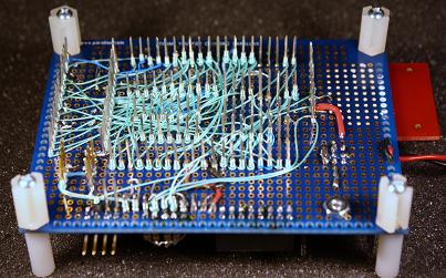
First Mini80 prototype, I used wire wrapping to interconnect ICs.
I wanted to keep the design as simple as possible, some thing I could put together in a week or two in my spare time. Constructing a "real" Z80 system generally requires a large number of supporting integrated circuits and a lot of interconnections between all the devices, not something you are going to hand build in a couple of evenings.
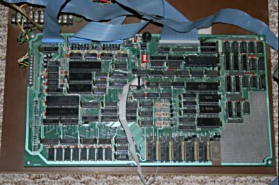
My original Big Board a "real" Z80 based CPM computer
The Z80 CPU is not an MCU and requires a number of external resources to operate. In specific the Z80 requires; RAM memory, a master clock, a boot loader, and I/O peripherals. The design I finally settled on was to use a Parallax Propeller chip to provide all the resources needed to run the Z80 CPU except for the RAM memory. In order to support the Z80 CPU I required 16 of the 32 I/O pins from the Propeller chip. This left 16 pins to support the emulation of the system peripherals such as RS232 serial ports, and floppy disk drives.
A Z80 based computer from the 1980s would have used dynamic RAM memory. By using a static CMOS RAM memory instead of dynamic memory the memory can be connected to the Z80 CPU without the need for external logic circuits. The RAM memory used in the Mini80 is a 128Kx8 static RAM. The design called for a 64K RAM however I could not locate a 64K RAM so I used the 128K RAM instead. The Z80 data lines (D0..D8) and address lines (A0..A15) connected directly to the RAM memory. The RAM selected line (/CE) is connected to the Z80 /MREQ line. The Z80 /RD and /WT lines are connected to the RAM memory using the 74LV367 non-inverting tri-state buffer. The buffer enable line is controlled by the Propeller chip and is used to tri-state the CPU /RD and /WT lines to allow operation of the boot loader.
The master clock for the Z80 is generated using a counter from the Propeller chip. The counter is used in NCO mode to allow the generation of a suitable frequency for the master clock. Generation of the master clock signal by the Propeller chip allows the clock to be manipulated during boot loader and I/O operations. Once the boot loader operation is completed by the propeller chip the Z80 is reset. After reset is completed, all Z80 op-codes that do not access an I/O port address are executed without intervention from the Propeller chip and the master clock runs at the required Z80 CPU speed.
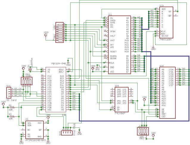
First Mini80 prototype schematic
The boot loader operation for a Z80 computer is normally performed using a ROM memory device such as an EPROM or EEPROM. The start code for the Z80 is placed into the ROM memory which is mapped to start at address zero. After a reset the Z80 will begin executing code at address zero. The memory space used by the ROM device is then mapped through external logic to be RAM memory. In the case of the Mini80 project there is no boot ROM memory and no external logic other then the tri-state buffer to boot strap the Z80 CPU. In the case of the Mini80 project the Propeller chip is used to control the Z80 and static RAM. The Propeller chip is connected to the Z80 data lines (D0..D7), /RESET line, /RD line, and master clock line. The propeller chip is also connected to the RAM memory /WT line. The steps used by the Propeller chip to boot strap the Z80 are as follows;
- Pull Z80 reset line low.
- Generate enough clock pulse to allow Z80 core to fully reset then set reset line high.
- Set the tri-state buffer enable pin high to tri-state Z80 read and write lines (/RD, /WT).
- Provide clock pulses to the Z80 until the Z80 indicates a read operation.
- Place the desire data on to the data buss, then pulse the RAM /WT pin low to write the memory location, Z80 provides address and RAM chip select.
- Place the 8 bit Z80 op-code NOP (0) on the data buss.
- Provide clock pulses to the Z80 until the Z80 indicates the read operation completed (/RD = high).
- Repeat steps 4..7 until the required boot code is copied to RAM, each cycle the Z80 will increment its memory address starting at address zero.
- Pull Z80 reset line low.
- Generate enough clock pulse to allow Z80 core to fully reset then set reset line high.
- Set the tri-state buffer enable pin low to enable Z80 read and write lines (/RD, /WT).
- Set the Propeller chip counter to clock the CPU at required frequency.
At this point the boot loader has completed and the Z80 will begin to execute the code loaded in to the RAM memory starting at memory address zero.
The Z80 CPU does not contain any peripherals. Instead the Z80 relies on external devices to perform all I/O operations. The external I/O devices are connected to the Z80 I/O buss. The Z80 I/O buss is an 8 bit data buss with 8 bit addressing allowing for up to 256 I/O addresses. The I/O memory addresses are often referred to a "I/O port addresses" or "ports". External logic is used to decode the selected port address and activate the desired I/O peripheral device. In the Mini80 project the Propeller chip emulates all the peripherals on the Mini80.
After the Propeller chip completes the boot loading of the Z80 it watches for a I/O port request from the Z80. When a port read or port write operation is requested by the Z80 the Propeller chip stops the Z80 master clock. The 74HC165 parallel to serial register is used to read the 8 bit port address from the Z80 address buss. If the Z80 requests a port write operation the 8 bit data value is read directly by the Propeller chip from the Z80 data buss. The Propeller chip uses the supplied port address and executes the required code to complete the request. If the Z80 performed a port read operation the resultant data is placed on the Z80 data buss and and the Z80 is clocked until the /RD line is set high by the Z80. If the Z80 performed a port write operation the Z80 is clocked until the /WT line is set high by the Z80. Finally the Propeller chip starts the Z80 master clock and goes back to waiting for an I/O port operation.
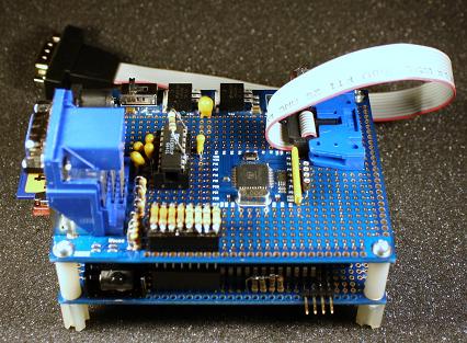
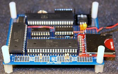
Mini80 prototype with I/O attached. PropTerm Ansi terminal and RS232 serial port mounted on top of Mini80.
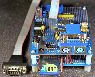
The Propeller chip is used to emulate 2 four wire serial ports, 1 two wire serial port, and 4 floppy disk drives. I hope to add an I2C port to the final software to allow for I/O expansion. For the first prototype I connected one of the four wire serial ports to a second Propeller board with VGA and PS2 support to run my PropTerm ANSI terminal. The second four wire serial port from the Mini80 is connected to a Max3232 3.3 volt RS232 driver attached to a DB9M connector. The SD card is connected to the Propeller chip on the Mini80 using four I/O pins with 100K ohm pull-up resistors. The SD card must be formatted as FAT16 or FAT32. All files used by the Mini80 must be in the root folder of the SD card.
The Mini80 CPM floppy disk images are stored in a file called "CPMDISK.CDP" on the SD card. The CPM disk pack file can contain from 4 to 128 CPM disk images. Each of the disk images is one megabyte in size and any CPM disk image can be mounted in any one of the four emulated disk drives. The CPM disk pack file must be contiguous on the SD card. It is currently mandatory that the CPM disk pack file be created on a freshly formatted SD card (no files or folders). All other files on the SD card do not have this restriction. I have modified the Z80Emu CPM emulator program to be able to manipulate the disk images in a disk pack file. See the article "Create and Manage Min80 Disk Pack Files" in the Z80Emu setion for more information.
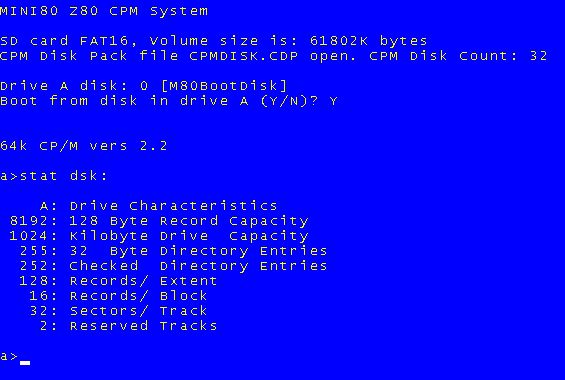
Mini80 running CPM 2.2. STAT command is run to display disk parameters.
I attempted to design the Mini80 to be loaded with CPM and its programs without the need for any custom software operating on another computer. All that is require is a computer that can format the SD card as FAT16 or FAT32 and copy files to the formatted SD card. At present the Mini80 can boot CPM from any one of the disk pack CPM floppy disk images.
If you initialize the Mini80 with a freshly formatted SD card the Mini80 will offer to create the CPM disk pack file. Once a new disk pack file is created the CPM disk image selected as virtual disk drive "A" needs the boot loader/CPM image placed on the CPM disk's reserved tracks. The system boot image contains a 256 byte boot loader followed by the CPM system image. The Mini80 can now load CPM from the selected boot disk in drive "A".
The Mini80 project can read a file named "M80BOOT.BIN" from the SD card that contains the system boot tracks (max 8K bytes). The boot track image can be copied to the disk pack CPM disk image selected as the boot disk (always CPM disk A). The Mini80 can also boot a Z80 monitor program stored on the SD card (max 6K bytes) in a file named "M80MON.BIN".
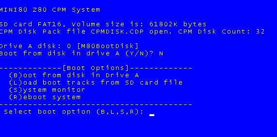
Min80 boot options menu
The Z80 CPU is rated for 5 volt operation. The Mini80 runs the Z80 using a 3.3 volt supply. To operate a CMOS device at a reduced voltage the max clock rate will generally have to be reduced. For the Mini80 project I looked to the only CPU based on the a ZILOG core that can operate at 5 to 3.3 volts, the S180. The S180 is rated at 33MHz at 5 volts and when operated at 3.3 volts the max clock frequency drops to 20 MHz. This should require that a CMOS Z80 max clock speed be de-rated by 20/33 to operate at 3.3 volts. As an example an 8 MHz Z80 should operate at; 8 * (20/33) = 4.85 MHz, and a 20 MHz Z80 CPU has a max clock frequency of; 20 *(20/33) = 12.12 MHz.
One feature of the Mini80 is the ability to clock the Z80 CPU at any speed from 100 KHz up to 20 MHz with a max clock frequency error of 0.2%. I tested a number of 6 MHz, 8 MHz and 10 MHz Z80 CPU chips in the Mini80. The 6 and 8 MHz Z80 chips had a max stable speed of 3.6 and 5.1 MHz respectively very close to the estimated max clock speeds. The 10 MHz Z80 chips tested on the Mini80 all ran stable up to 10.2 MHz. I believe the most likely reason is that the parts are stamped 10 MHz but actually contain 16 MHz dies. A 16 MHz Z80 CPU should operate at 9.6 MHz max clock rate at 3.3 volts.
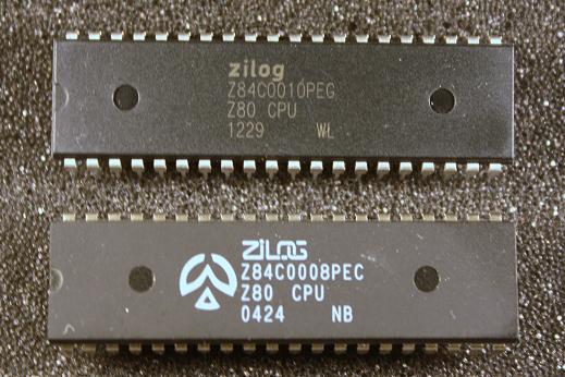
8 MHz and 10 MHz Z80 CPUs
At present the Mini80 can boot CPM and run most text based CPM software. The Mini80 is currently running the Z80 at 10Mhz and it is very stable. I do not know why I was not forced to de-rate the Z80 clock frequency to compensate for the lower operating voltage. The software is nearly completed and I have posted all relevant source file. The Mini80 first prototype downloads contains the project source files. There are a number of CPM related articles on the site that may be of help in using CPM.